Air Quality Insights

Regulatory
Understanding the Implications of the EPA's Strengthened Air Quality Standards
Explore the technical nuances and practical implications of the EPA's recent announcement regarding strengthened air quality standards.

HEALTH
Improving Air Purity and Health Outcomes: 5 Crucial Considerations
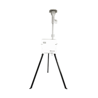
Explore the crucial factors to evaluate when implementing air quality monitoring programs at the state and local levels. Discover Mesa Labs' advanced solutions, including the EPA-recognized PQ series, ensuring accurate and reliable measurements for improved community health and safety.